How to Draw Network Diagram in Ms Project
![]()
Using Network Diagrams in Project
To see the Network Diagram, on the View tab of the Ribbon click Network Diagram.
The Descriptive Network Diagram view is identical to the Network Diagram view, except for the size, and the detail of the boxes that correspond tasks. The boxes on the Descriptive Network Diagram view are larger and can incorporate labels for the data elements in the box. These larger boxes take up more infinite, and thus fewer boxes fit on a printed page.
For instructor-led MS Project grooming in Los Angeles call us on 888.815.0604.
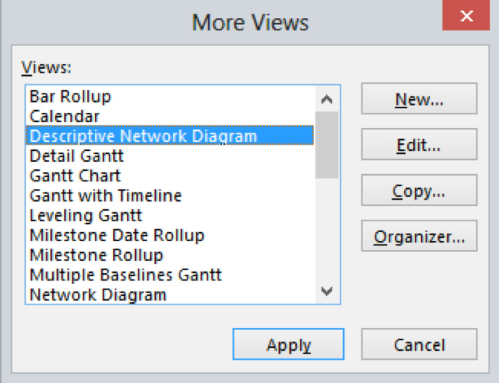
To display the Descriptive Network Diagram view, click the Other Views command on the View tab, select More than Views and then select the Descriptive Network Diagram:
Network Diagrams (the PERT Chart principle)
The term PERT is derived from Programme Evaluation and Review Technique which was invented for the management of Projects by paper based systems. The NETWORK DIAGRAM which has evolved from the PERT Chart is a diagrammatic view of the tasks where the position of the task and the lines linking them together represent the detailed steps that contain the project. The Network Diagram view displays tasks and task dependencies in a network or flowchart format. A box (sometimes chosen a node) represents each task, and a line connecting ii boxes represents the dependency betwixt the 2 tasks.
It is possible to create a new project in the Network diagram or modify an existing project by adding and linking tasks.
- To create a new task, in an empty part of the Network diagram drag a rectangle shape with your mouse - a new node will appear set up for you to type in the details
- To create a new task that is linked to an existing task, click the existing chore and drag with your mouse to an empty part of the diagram - a new node volition appear ready for you to blazon in the details.
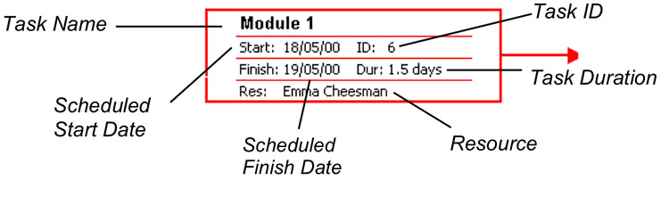
The Network Box (or Node)
A Network box consists of five fields, as illustrated below. The Job Name, Task ID, Scheduled Get-go Date, Scheduled Finished Date, and Chore Duration are the default fields in the Network box. The Task Name field is white considering it is currently ready for user input.
Change how the nodes are displayed
Annotation: By default, the network diagram shows disquisitional tasks in cherry-red and displays i diagonal line through a task that is in progress and crossed diagonal lines through a completed chore.
- On the Format tab, click Box Styles.
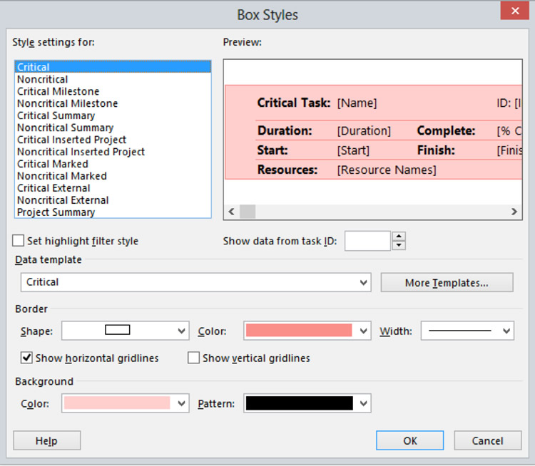
- In the Style settings for list, click the chore category whose content and advent you desire to change.
- Cull a different Data template - which changes what information is displayed on the node:
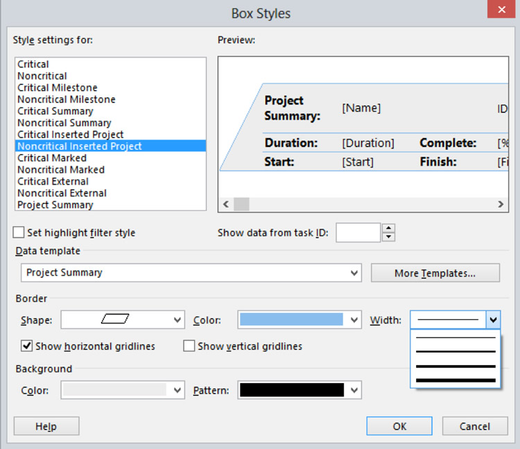
- Under Border, cull the shape, colour, width, and gridline options to create the wait you want.
- Under Background, cull the required colour and pattern.
- Click OK.
Get a 60-mean solar day trial version of Projection 2022 Professional.
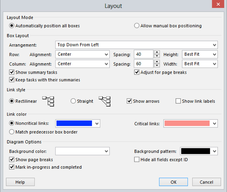
Adjust the diagram layout
Depending on the structure of your projection, the number of summary tasks and subtasks and the number and types of task links, the Network Diagram boxes may not be arranged as you expected. You can modify the layout by applying unlike box arrangements, adjusting various layout parameters, and applying one of ii different link styles:
- On the Format tab, click Layout.
- Nether Box Layout, in the Arrangement list, click how you want the boxes to be arranged.
- For rows and columns, specify alignment, spacing, height, and width in the corresponding boxes.
- To space boxes evenly, click Fixed in the Elevation and Width boxes.
Note: If you can't conform Network Diagram boxes the style you want, you may want to position them manually: Click Allow manual box positioning, click OK, and so elevate the boxes to the location y'all desire.
Alter the link line style
If yous have many tasks that are linked to a predecessor or task, the link lines tin overlap and be difficult to read in the Network Diagram view. Y'all can alter the manner of the link lines and adjust them how yous want. Y'all tin besides display task dependency labels on the link lines.
On the Format tab, click Layout:
- To brandish link lines equally straight lines between predecessor and successor task boxes, under Link way, click Direct.
- To display link lines as horizontal and vertical line segments continued at right angles between predecessor and successor chore boxes, under Link style, click Rectilinear.
- To display labels on link lines identifying the chore dependency and any pb or lag time nether Link fashion, select the Show link labels check box.
- To brandish link lines with arrows indicating the predecessor and successor of tasks, under Link style, select the Prove arrows check box.
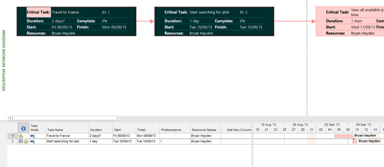
The Network Diagram in a combination view
A combination view contains two views. The view in the bottom pane shows detailed data well-nigh the tasks or resources you select in the view in the top pane. For instance, yous tin have the Gantt Nautical chart view in the top pane and the Task Grade view in the bottom pane. When you select a job in the upper view, the Job Form view displays detailed information about that task. The same applies to Network Diagrams.
In the illustration below the selected job is shown in particular in the lower pane where the Task Usage view is displayed:
To split the screen
- On the View tab of the ribbon check the Details box
- Click the drop down arrow to choose the Detail you wish to display.
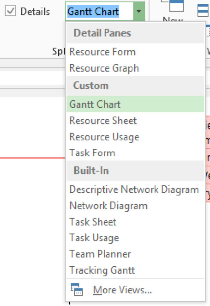
Note: to remove the split, uncheck the Details box.
Navigating the Network Diagram
The table below summarises how to motility effectually the Network Diagram with your keyboard and with your mouse.
| Movement | Keys | Mouse |
| To a different NETWORK box | Arrow keys | Click the NETWORK box |
| Next field in NETWORK box | Tab or Enter | Click the field |
| Previous field in NETWORK box | Shift+Tab or Shift+Enter | Click the field |
| Page upward or page down | Page Up or Page Down | On the vertical coil bar, click the gray area above or beneath the curl box |
| Folio to the left or right | Ctrl+Page Upwards or Ctrl+Folio Down | On the horizontal scroll bar, click the gray area on the left or right of the scroll box to curl left or right in increments |
| To upper-left NETWORK box in projection | Home | |
| To lower-right NETWORK box in project | Stop | |
| To upper-left NETWORK box on screen | Ctrl+Abode | |
| To lower-right NETWORK box on screen | Ctrl+Cease |
Also run into using tables in MS Project.
Source: https://www.trainingconnection.com/project/lessons/network-diagrams.php
Post a Comment for "How to Draw Network Diagram in Ms Project"